Understanding the common problems in processing CNC turned parts is essential for ensuring high-quality manufacturing.
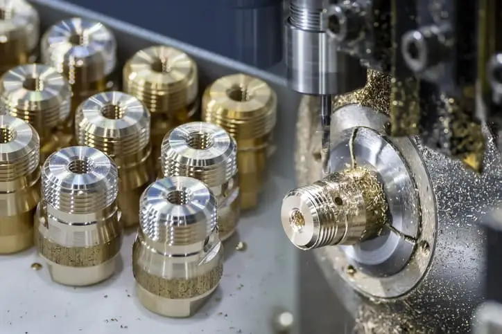
CNC Turned Parts: Common Processing Challenges
1. Workpiece Deformation
1.1 Causes Analysis
- Improper Clamping Force: Concentrated pressure from rigid clamping (e.g., single-point force of 3-jaw chuck) leads to elastic deformation; uneven force on thin-walled/irregular workpieces may cause plastic deformation, resulting in dimensional rebound after unclamping.
- Cutting Heat Accumulation: Approximately 70% of cutting heat is transferred to the workpiece, causing thermal expansion and contraction (e.g., steel thermal expansion coefficient: 11×10⁻⁶/℃). Continuous rough and finish machining prevents heat dissipation, leading to dimensional deviations (e.g., axial elongation of long shafts, expanded inner diameter).
1.2 Solution Operations
- Soft Jaw Adaptation & Segmented Clamping:
- Customize soft jaws per workpiece contour (e.g., arc jaws for round workpieces, V-jaws for shafts) to increase contact area by over 30% and avoid local overpressure.
- Control segmented clamping spacing at 1/3~1/2 of workpiece length; for shafts with length-diameter ratio >5, adopt “two-end support + middle auxiliary clamping” and set clamping force to 10%~15% of material yield strength (e.g., ≤80MPa for 45# steel).
- Separation of Rough/Fine Machining & Allowance Reservation:
- Remove 80%~90% of allowance in rough machining, leaving 0.1~0.3mm for finish machining (0.05~0.15mm for thin-walled parts); shut down to cool to room temperature (15~30 minutes, adjusted by workpiece size) after rough machining.
- Adopt small cutting depth (0.02~0.05mm) and high cutting speed in finish machining to reduce heat generation.
- Expansion Fixtures for Thin-Walled Parts:
- Use hydraulic expansion chucks or elastic collets to replace rigid clamping with uniform expansion force (0.02~0.05mm expansion); fill thin-walled tubes (wall thickness <3mm) with low-melting-point alloy or polyurethane to enhance rigidity.
2. Tool Vibration/Wear
2.1 Causes Analysis
- Insufficient Tool Shank Rigidity: Tool shanks with length-diameter ratio >5 cause bending vibration (chatter) under cutting force, leading to poor surface waviness; low-strength shank materials (e.g., ordinary carbon steel) amplify vibration amplitude.
- Unreasonable Cutting Parameters: Excessively high cutting speed causes high-temperature tool edge wear; excessive feed rate sharply increases cutting force, both accelerating tool chipping and built-up edge formation, thus affecting precision.
2.2 Solution Operations
- Tool Shank Selection & Rigidity Optimization:
- Prioritize short and thick shanks (length-diameter ratio ≤5:1) made of cemented carbide or alloy steel; shank diameter should be 20%~30% smaller than the machining hole (for internal hole machining), and extension length ≤3×shank diameter (for external turning).
- Use anti-vibration shanks (with built-in dampers) for deep cavity/hole machining to reduce vibration amplitude by ≥40%.
- High-Feed Tools & Parameter Matching:
- Select high-feed tools (e.g., corn cutters, high-feed turning tools) for rough machining with cutting depth 1~3mm and feed rate 0.2~0.5mm/r to reduce cutting force via high feed and small depth.
- Match parameters to materials: Carbon steel (100~150m/min, 0.1~0.2mm/r), stainless steel (50~80m/min, 0.05~0.1mm/r), aluminum alloy (300~500m/min, 0.15~0.3mm/r).
- Tool Wear Monitoring & Compensation:
- Replace tools immediately when tip wear >0.2mm or built-up edge/chipping occurs.
- Adjust X/Z-axis offsets via machine tool compensation (0.01~0.02mm per adjustment) to correct dimensional deviations from wear.
3. Low Precision of Internal Hole Machining
3.1 Causes Analysis
- Tool Shank Limitations: Internal hole machining reduces shank rigidity by over 50% compared to external turning, prone to vibration; oversized shanks restrict chip evacuation space, causing chip clogging, secondary cutting, hole wall scratches, and dimensional errors.
- Poor Chip Evacuation: Chips cannot be discharged promptly in blind/deep hole machining, squeezing the tool edge and leading to expanded diameter and excessive roundness error (e.g., >0.01mm).
3.2 Solution Operations
- Internal Cooling Tools & Chip Evacuation Assistance:
- Use turning tools with internal cooling channels; high-pressure cutting fluid (pressure ≥10MPa) is sprayed directly to the cutting area to remove chips and cool the tool.
- Adopt spiral groove shanks for blind hole machining to facilitate chip discharge; retract multiple times for hole depth >5×diameter.
- Shank-Hole Diameter Matching:
- Shank diameter should be 60%~70% of the hole diameter (e.g., φ12~14mm shank for φ20mm hole) to reserve 30%~40% chip space.
- Use gun drills or BTA deep hole drills with high-pressure external chip evacuation for deep holes (depth >10×diameter).
- Micro-Cutting Process Optimization:
- Reduce feed rate to 0.02~0.05mm/r and cutting depth to 0.05~0.1mm; adopt “multiple micro-cutting” instead of single large-depth cutting.
- Perform “finishing cut” (0.01~0.02mm depth) as the final pass to improve surface roughness (Ra≤0.8μm) and roundness (≤0.005mm).
4. Thread Machining Chaos/Poor Precision
4.1 Causes Analysis
- Machine Synchronization Error: Asynchronous spindle speed and Z-axis feed cause lead deviation (e.g., >0.02mm/100mm); excessive ball screw backlash (>0.01mm) results in thread disorder and uneven pitch.
- Tool Edge Wear: Worn thread tool edges cause profile half-angle deviation (e.g., standard 60° profile becomes 58° or 62°), leading to pitch diameter over-tolerance and failure in thread gauge inspection.
4.2 Solution Operations
- Machine Synchronization Precision Calibration:
- Adjust the synchronization coefficient between the spindle encoder and Z-axis servo motor via machine parameters to ensure lead error ≤0.01mm/100mm.
- Detect and compensate for ball screw backlash (input measured value 0.002~0.005mm via the machine’s backlash compensation function) to eliminate reverse clearance.
- Special Tools & Trial Cut Compensation:
- Select dedicated tools per thread type (e.g., 60° profile tools for metric threads, 55° for imperial threads); use cemented carbide for mass production or high-speed steel.
- Measure pitch diameter and pitch with a thread micrometer after 1~2 trial cuts; correct via X-axis tool offset (0.005mm offset per 0.01mm pitch diameter deviation).
- Quality Control in Mass Production:
- Inspect every 10~20 workpieces with thread go/no-go gauges; pass if the go gauge screws in smoothly and the no-go gauge penetrates ≤2 turns.
- Use the three-wire measurement method for high-precision threads (e.g., tolerance class 6H/6g) to adjust tool compensation timely.
5. Stainless Steel/Aluminum Workpiece Tool Adhesion
5.1 Causes Analysis
- Stainless Steel Characteristics: Austenitic stainless steel (e.g., 304, 316) has high toughness and poor thermal conductivity (1/3 of carbon steel), leading to prolonged chip-tool contact and high-temperature adhesion (built-up edge) during cutting, which dulls the tool edge.
- Aluminum Characteristics: Soft and oxidizable aluminum forms an oxide film (Al₂O₃) during cutting, which adheres to the tool edge as built-up edge, affecting thread profile and internal hole quality.
5.2 Solution Operations
- Stainless Steel Machining Plan:
- Tool Selection: Use cemented carbide tools containing 8%~12% cobalt (e.g., YG8, YT15); cobalt enhances high-temperature stability and wear resistance.
- Cutting Fluid: Adopt extreme pressure emulsion (with sulfur-phosphorus additives) for cooling and lubrication, reducing cutting temperature by over 30%.
- Cutting Parameters: Increase cutting speed to 80~120m/min (20% higher than carbon steel) and set feed rate to 0.08~0.15mm/r to reduce chip-tool contact time.
- Aluminum Machining Plan:
- Tool Selection: Prioritize PCD (polycrystalline diamond) tools with high hardness (HV8000+) and low friction coefficient (0.05~0.1) to avoid adhesion.
- Cutting Fluid: Use aluminum-specific cutting fluid (chlorine-free, low viscosity) to prevent corrosion, or dry cutting for finish machining to avoid fluid residue-induced adhesion.
- Edge Treatment: Apply a 0.02~0.05mm chamfer to the tool edge to maintain sharpness and reduce built-up edge; clean aluminum chips from the tool surface promptly after machining.
If you are looking for a CNC processing solution, please visit us here https://hktl-fastener.com/cnc-machining-parts/.