
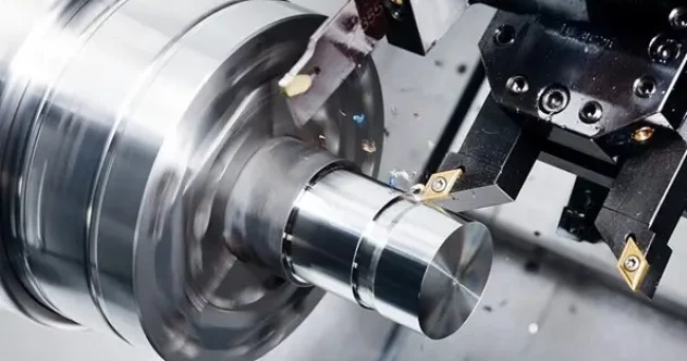
Turning is a cutting process in which the workpiece rotates and the lathe tool moves in a straight line or along a curve in a plane. Turning is usually carried out on a lathe and is used to machine the inner and outer cylindrical surfaces, end faces, conical surfaces, formed surfaces and threads of the workpiece, etc.
I. Turning
Turning is a cutting process in which the workpiece rotates and the lathe tool moves in a straight or curved path within a plane. Turning is usually performed on a lathe and is used to machine the inner and outer cylindrical surfaces, end faces, conical surfaces, formed surfaces and threads of the workpiece, etc.
The surface roughness of the machined surface by turning is generally 1.6 – 0.8 μm.
1)In rough turning, it is aimed to enhance the turning efficiency by adopting a large cutting depth and a large feed rate without reducing the cutting speed, with the surface roughness being Rα20—10μm.
2) For semi-finishing and finishing turning, high speed and small feed rate and cutting depth should be adopted as much as possible, with surface roughness ranging from Rα10 to 0.16 μm.
3) On a high-precision lathe, when using a finely ground diamond turning tool to perform high-speed finish turning on non-ferrous metal parts, the surface roughness can reach Rα 0.04 – 0.01 μm.
II. Milling
Milling is a highly efficient processing method that involves cutting workpieces with a rotating multi-edge tool. It is suitable for machining flat surfaces, grooves, various formed surfaces (such as splines, gears, and threads), and special-shaped surfaces of molds. According to whether the direction of the main motion speed during milling is the same as or opposite to the feed direction of the workpiece, it can be further classified into up milling and down milling.
The surface roughness of the machined surface by milling is generally 6.3 – 1.6 μm.
The surface roughness Rα is 5—20 μm during rough milling.
The surface roughness Rα is 2.5 – 10 μm during semi-finish milling.
The surface roughness Rα is 0.63 – 5 μm during finish milling.
III. Planing
Planing is a cutting process in which a planing tool moves in a horizontal, linear, and reciprocating motion relative to the workpiece. It is mainly used for shaping the external surfaces of parts.
The surface roughness of planing is generally Ra6.3 – 1.6 μm.
The surface roughness after rough planing is 25 – 12.5 μm.
The surface roughness of semi-precision planing is 6.2 – 3.2 μm.
The surface roughness of the finish planing is 3.2 – 1.6 μm.
IV. Grinding
Grinding is a machining method that uses abrasives and grinding tools to remove excess material from workpieces. It is a kind of precision machining and is widely applied in the mechanical manufacturing industry.
Grinding is usually employed for semi-finishing and finishing operations, with surface roughness typically ranging from 1.25 to 0.16 μm.
The surface roughness of precision grinding is 0.16 – 0.04 μm.
2) The surface roughness of ultra-precision grinding is 0.04 – 0.01 μm;
The surface roughness of mirror grinding can reach below 0.01 μm.
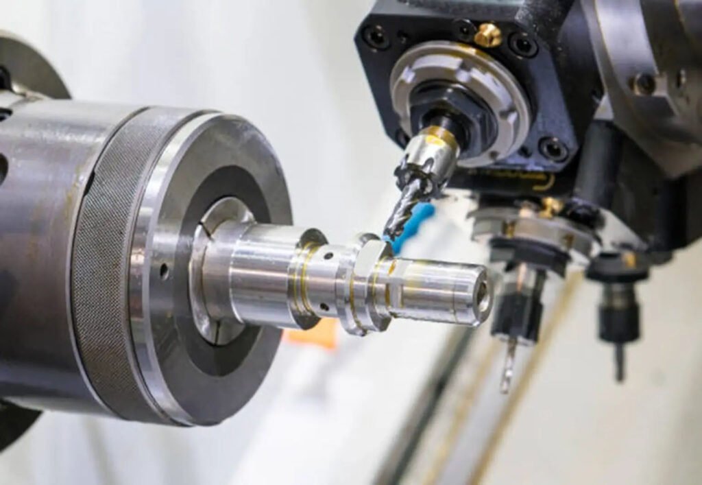
V. Drilling
Drilling is a basic method of hole machining. Drilling is often carried out on drilling machines and lathes, and can also be performed on boring machines or milling machines.
The surface roughness of drilling is generally 12.5 – 6.3 μm. After drilling, reaming and boring are often used for semi-finishing and finishing.
VI. Boring
Boring is a cutting process that uses a tool to enlarge the inner diameter of a hole or other circular profile. Its application range generally covers from semi-finishing to finishing, and the tools used are typically single-edge boring tools (referred to as boring bars).
1)The boring accuracy of steel materials can generally reach IT9 – IT7, and the surface roughness is 2.5 – 0.16 μm.
2) The machining accuracy of precision boring can reach IT7 – IT6, and the surface roughness is 0.63 – 0.08 μm.
Metal material processing coefficient table, comprehensively understand the material performance data that needs to be known before processing.
I. Steel Processing Coefficient Table
1. High-speed Steel Cutting Coefficient Table
In the high-speed steel cutting coefficient table, the main parameters we need to understand are: cutting speed, cutting depth, cutting width, and processing volume, etc. Relevant data can be referred to in the following table:
| Material Name | Cutting Speed (m/min) | Cutting Depth (mm) | Cutting Width (mm) | Processing Volume (mm/min) |
| 45 Steel | 20 – 40 | 0.2 – 1 | 1 – 3 | 20 – 50 |
| 4Cr5MoSiV | 18 – 30 | 0.2 – 1 | 1 – 3 | 30 – 50 |
| 65Mn | 20 – 50 | 0.5 – 3 | 2 – 5 | 50 – 400 |
| GCr15 | 8 – 12 | 0.05 – 0.2 | 1 – 2 | 4 – 6 |
2. Cold Hardening Steel Machining Coefficient Table
In the cold hardening steel machining coefficient table, the main parameters we need to understand include: cutting speed, cutting depth, cutting width, and machining volume. Relevant data can be referred to in the following table:
| Material Name | Cutting Speed (m/min) | Cutting Depth (mm) | Cutting Width (mm) | Machining Volume (mm/min) |
| 9SiCr | 10~20 | 0.05-0.1 | 0.5~1 | 10~20 |
| 65Mn | 8~20 | 0.05-0.5 | 0.5~1 | 10~20 |
| GCr15 | 6~12 | 0.05-0.2 | 0.5~1 | 5~10 |
II. Aluminum Material Processing Coefficient Table
In the aluminum material processing coefficient table, the main parameters we need to understand include: cutting speed, cutting depth, cutting width, and processing volume, etc. Relevant data can be referred to in the following table:
| Material Name | Cutting Speed (m/min) | Cutting Depth (mm) | Cutting Width (mm) | Processing Volume (mm/min) |
| 1060 Aluminum Plate | 30 – 80 | 0.5 – 3 | 1 – 3 | 50 – 200 |
| 7075-T6 Aluminum Alloy Plate | 15 – 50 | 0.5 – 3 | 1 – 3 | 25 – 100 |
| 2024-T3 Aluminum Alloy Plate | 30 – 80 | 0.5 – 4 | 1 – 3 | 40 – 200 |
III. Copper Processing Coefficient Table
In the copper processing coefficient table, the main parameters we need to understand are: cutting speed, cutting depth, cutting width, and processing volume. Relevant data can be referred to in the following table:
| Material Name | Cutting speed (m/min) | Cutting depth (mm) | Width (mm) | Processing speed (mm/min) |
| C10200-O (Soft Copper) | 25 to 90 | 0.05 to 5 | 1 to 3 | 20 to 10 |
| C26000-H (Brass) | Twenty to eighty | 0.05 to 5 | 1 to 3 | 10 to 70 |
| C36000-H (Free-cutting Brass) | 50 to 20 | 0.05 to 5 | 1 to 3 | 40 to 250 |
Based on the above table of machining coefficients for various metal materials, we can have a more comprehensive understanding of the machining parameters for different types of metal materials.
This is of great significance for the necessary material adjustment and program optimization before machining, which can enhance the efficiency and quality of the machining process.
If you are looking for a reliable CNC processing solution, please visit us here https://hktl-fastener.com/cnc-machining-parts/.
